Flask Demo Application to Showcase R&S SMW200A MIMO Fading Features

Project study conducted at Rohde & Schwarz

Topics covered:

Motivation → Theory MIMO → Vector RF Signal Generators → Demonstration Application

The evolution of mobile communications is driven by major architectural advances that continuously reshape how we connect and communicate.

LTE (4G): unified voice, video, messaging, and data over IP networks.

5G: expanded mobile communications to new domains such as autonomous driving, Industry 4.0, AR, and smart cities.

6G: expected around 2030, with AI-native orchestration and integrated sensing and communication (ISAC).

As networks become more complex, realistic testing and accurate channel emulation become increasingly important.

As a manufacturer of test and measurement equipment, Rohde & Schwarz must ensure that its instruments can bridge theoretical concepts and practical implementation challenges.

Objective of this Project
Develop a proof-of-concept demonstration application that integrates realistic digital-twin MIMO fading simulations into the Rohde & Schwarz SMW200A.

What is MIMO about?

Multiple-input multiple-output (MIMO) systems use multiple transmit and/or receive antennas to improve wireless communication performance.

Two Main Benefits of MIMO

(i) Spatial diversity: improves reliability by combining signal energy from multiple antennas, which can reduce transmission errors and improve the effective SNR.

(ii) Spatial multiplexing: increases data rate by transmitting multiple independent data streams simultaneously over the same channel resources.

The maximum number of simultaneously transmitted independent streams is limited by the smaller number of antennas at the transmitter or receiver.

Example
A 2×2 and a 4×2 MIMO system can both support at most two spatial streams. The 4×2 system, however, offers additional spatial diversity, which can improve reliability and overall performance.

2×2 Narrowband MIMO Channel Model

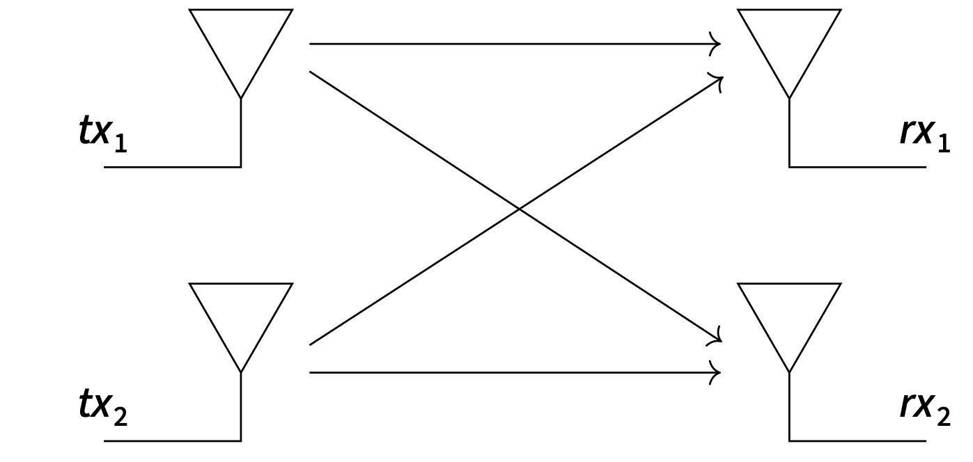
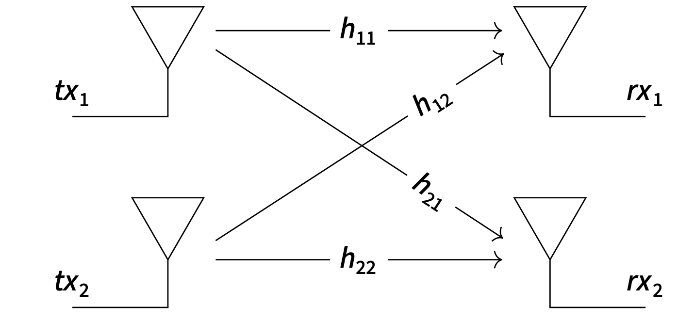
2×2 MIMO transmission model.

The simplest non-trivial MIMO system uses 2 transmit (tx) and 2 receive (tx) antennas.

Its input-output relation is described by:

\[ \begin{bmatrix} y_1\\ y_2 \end{bmatrix} = \begin{bmatrix} h_{11} & h_{12}\\ h_{21} & h_{22} \end{bmatrix} \begin{bmatrix} x_1\\ x_2 \end{bmatrix} + \begin{bmatrix} n_1\\ n_2 \end{bmatrix} \]

In compact form: \( \mathbf{y} = \mathbf{H}\mathbf{x} + \mathbf{n} \)

Each coefficient \( h_{ij} \) denotes the complex channel gain from transmit antenna \( j \) to receive antenna \( i \).

Assumption: Flat Fading
The model assumes a narrowband or flat-fading channel, meaning the channel response is approximately constant over the signal bandwidth. Under this assumption, noise is modeled as additive white Gaussian noise (AWGN).

When is spatial multiplexing possible?

Spatial multiplexing is feasible only if the receiver can reliably recover the transmitted signal vector \( \mathbf{x} \) from the received vector \( \mathbf{y} \).

If the channel matrix \( \mathbf{H} \) is rank-deficient, the transmitted streams cannot be uniquely separated.

However, rank alone is not sufficient: even a full-rank channel may be difficult to invert if it is poorly conditioned.

Condition Number
The condition number \[ \kappa = \frac{\sigma_{\max}}{\sigma_{\min}} \] measures how suitable the channel is for spatial multiplexing.

\(\kappa \approx 1\): well-conditioned channel, good stream separability
large \(\kappa\): poorly conditioned channel, high sensitivity to noise and interference

Singular Value Decomposition of the Channel Matrix

The singular value decomposition (SVD) reveals the structure of the MIMO channel:

\[ \mathbf{H} = \mathbf{U}\,\mathbf{\Sigma}\,\mathbf{V}^H \]

Here, \( \mathbf{U} \) and \( \mathbf{V} \) are unitary matrices, and \( \mathbf{\Sigma} \) is a diagonal matrix containing the singular values \( \sigma_1, \sigma_2 \).

Geometrically, the channel action can be interpreted as: rotation \(\rightarrow\) scaling \(\rightarrow\) rotation.

This decomposition decouples the MIMO channel into parallel independent sub-channels, where each singular value represents the effective gain of one sub-channel.

Connection to Eigendecomposition
The right singular vectors are obtained from \[ \mathbf{H}^H \mathbf{H} = \mathbf{V}\,\mathbf{\Lambda}\,\mathbf{V}^H \] with eigenvalues \( \lambda_i = \sigma_i^2 \), and the left singular vectors follow from \[ \mathbf{u}_i = \frac{1}{\sigma_i}\mathbf{H}\mathbf{v}_i. \]

MIMO Channel Capacity

The channel capacity describes the maximum achievable spectral efficiency under ideal coding and arbitrarily small error probability.

General Expression
For zero-mean Gaussian input \( \mathbf{x} \) with covariance \( \mathbf{C}_{\mathbf{x}} = E\{\mathbf{x}\mathbf{x}^H\} \) and AWGN with covariance \( \mathbf{C}_{\mathbf{n}} = \sigma^2 \mathbf{I} \), \[ C(\mathbf{H}) = \log_2 \det \left( \mathbf{I} + \mathbf{C}_{\mathbf{n}}^{-1}\mathbf{H}\mathbf{C}_{\mathbf{x}}\mathbf{H}^H \right) \quad \left[\frac{\text{bits}}{\text{s}\cdot\text{Hz}}\right] \]
No CSI at the Transmitter
If the transmitter has no channel state information, power is equally distributed: \( \mathbf{C}_{\mathbf{x}} = \frac{P}{n_t}\mathbf{I}, \qquad \rho = \frac{P}{\sigma^2} \) which gives \[ C(\mathbf{H}) = \log_2 \det \left( \mathbf{I} + \frac{\rho}{n_t}\mathbf{H}\mathbf{H}^H \right) \]

Capacity grows logarithmically with SNR and can increase roughly linearly with \( \min(n_t, n_r) \) when the channel supports spatial multiplexing.

Channel Estimation and Simulation

Why It Matters
Realistic fading scenarios are essential for evaluating receiver robustness, spatial multiplexing performance, and overall system reliability under practical operating conditions.

In wireless systems, reliable transmission is challenged by fading, i.e., random fluctuations of signal amplitude and phase over time, frequency, and space.

Fading is caused by multipath propagation: the transmitted signal reaches the receiver over multiple paths with different delays, phases, and attenuations, resulting in constructive and destructive interference.

In MIMO systems, this effect becomes even more complex because each transmit–receive antenna pair experiences a different channel realization.

Standardized Testing
3GPP specifies standardized conducted fading tests for device certification, ensuring that user equipment is evaluated under realistic and reproducible channel conditions.

Channel Modeling Approaches

Empirical / Standardized Models
3GPP channel models such as SCM, SCME, and the models in TR 36.873 and TR 38.901 are based on extensive measurement campaigns.

They define realistic parameters such as delay spread, angular spread, path loss, and spatial correlation for scenarios like UMa, UMi, RMa, and InH.

Ray Tracing / Digital Twins
Ray tracing is a deterministic, geometry-based approach that models propagation effects such as reflection, diffraction, and scattering using a detailed 3D representation of the environment.

It enables highly accurate, site-specific channel simulation and is especially useful for beamforming, millimeter-wave, and sub-THz studies.

Key Distinction
Empirical models provide standardized, reproducible test conditions for fair comparison, while ray tracing provides scenario-specific, high-fidelity propagation insight.

Analog vs. Vector Signal Generators

The key difference lies in the type of waveform they can generate.

Analog Signal Generators
Output: continuous-wave signals
Modulation: AM, FM, PM
Strengths: simplicity, purity, cost
Vector Signal Generators
Output: arbitrary I/Q waveforms
Modulation: digital and complex standards-based signals
Strengths: flexibility, realism, channel emulation
Why This Matters
Modern wireless testing requires vector signal generators because realistic communication signals are defined by time-varying amplitude and phase.

Vector Signals and I/Q Representation
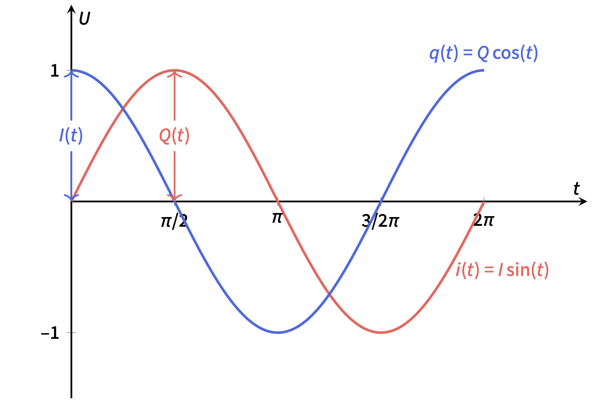
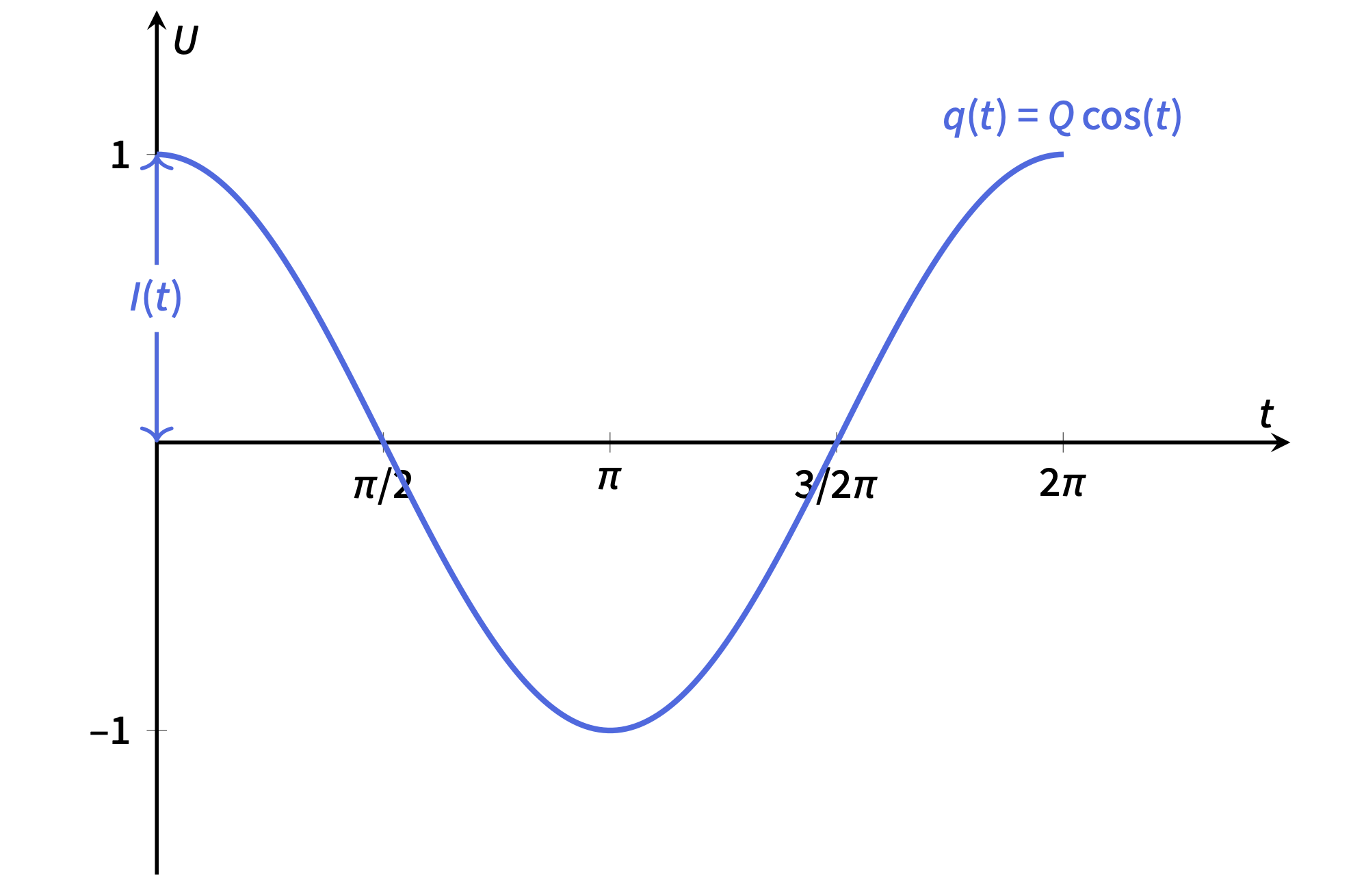
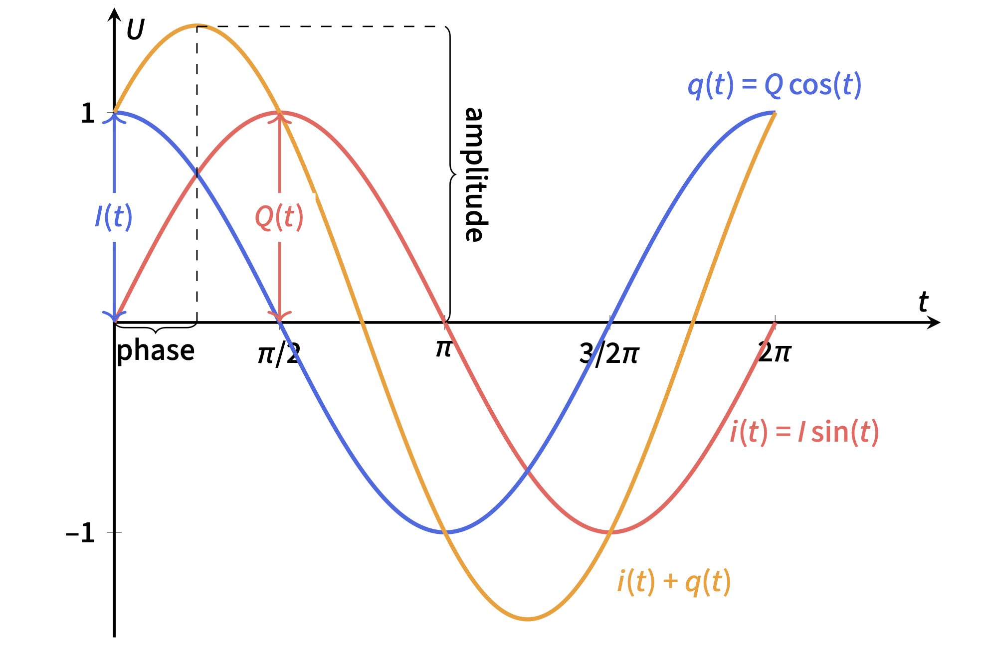
Superposition of two sinusoidal signals in quadrature.

Vector Signal Representation

A vector signal is characterized by its instantaneous amplitude and phase.

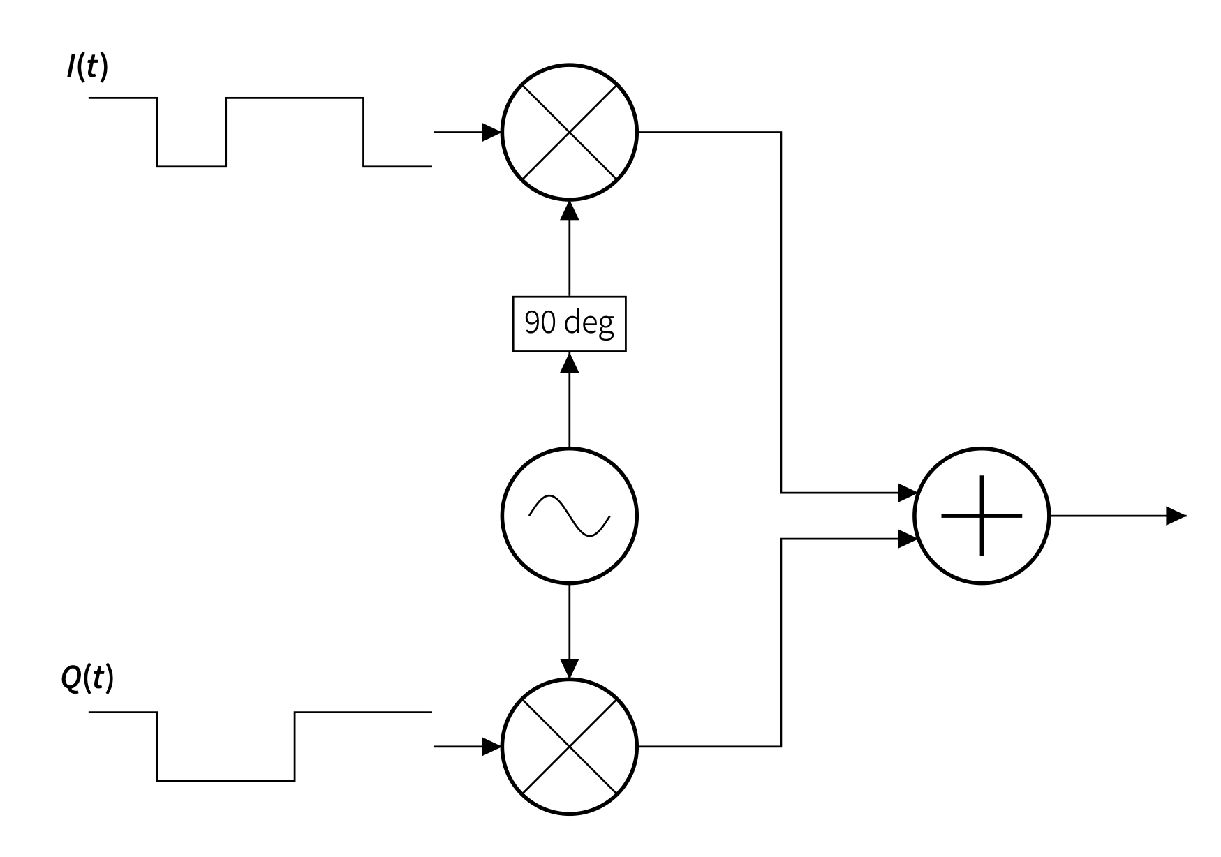
Such a signal can be represented as the superposition of two orthogonal carrier components with the same frequency and a phase offset of \(90^\circ\).

These components are denoted as \(I(t)\) (in-phase) and \(Q(t)\) (quadrature).

By controlling \(I(t)\) and \(Q(t)\), the resulting RF signal can be generated with precisely defined amplitude and phase.

Why This Matters
Vector signal generators create complex communication waveforms by controlling the time-varying I/Q components of the carrier.

Digital Modulation Using I/Q States

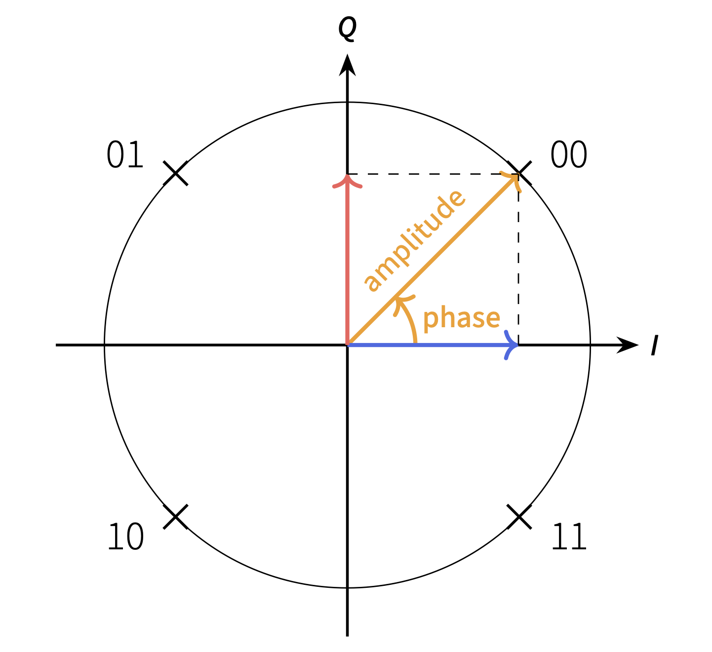
QPSK constellation diagram.
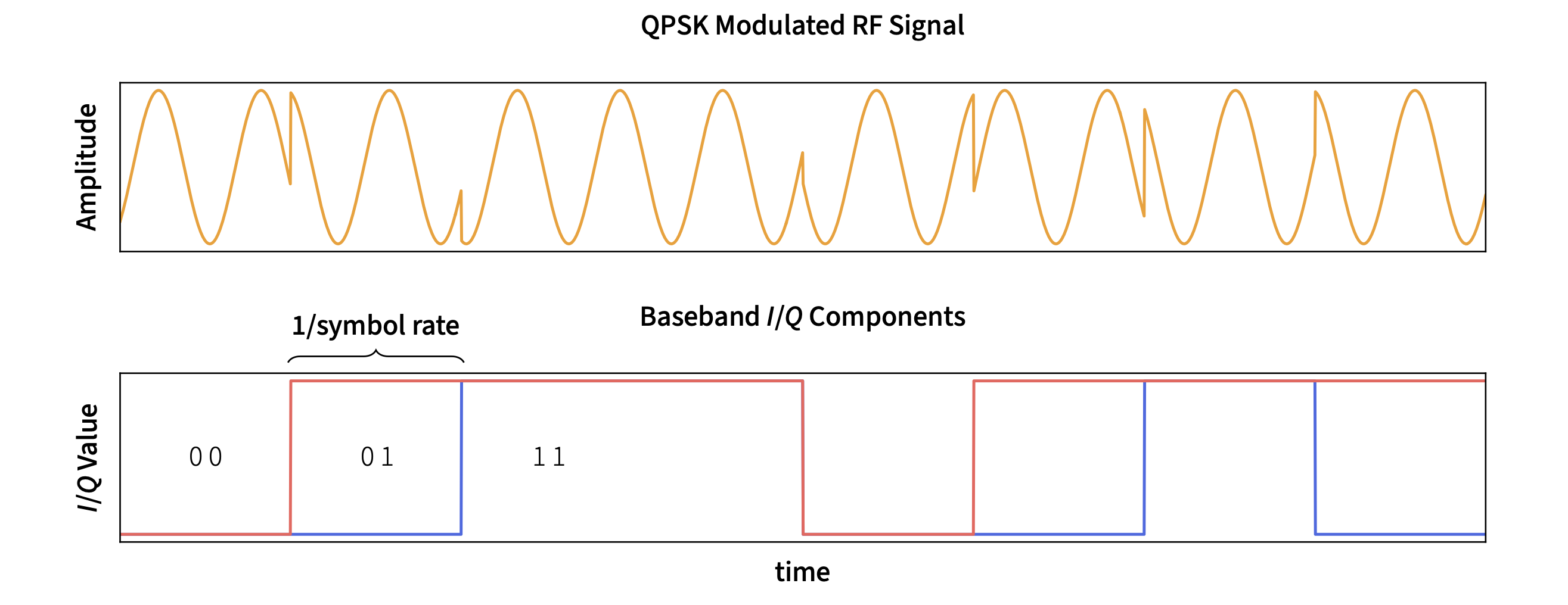
QPSK-modulated RF carrier over time.

Digital modulation conveys information by mapping bits onto discrete signal states defined by amplitude and phase.

In the I/Q plane, each state corresponds to a specific pair of values \( (I, Q) \).

Example: QPSK
In quadrature phase-shift keying (QPSK), the carrier phase takes one of four discrete states. Each symbol therefore represents 2 bits.
Higher-Order Modulation
QAM increases the number of bits per symbol by varying both amplitude and phase. For example, 64-QAM uses 64 distinct I/Q states and encodes 6 bits per symbol.
Practical Use
Modern wireless systems often use adaptive modulation, selecting the modulation order according to current channel conditions to balance throughput and robustness.

Vector Signal Generation

Basic operation principle of a I/Q modulator.
Vector Signal Generator Signal Processing Chain Block diagram showing Baseband, Signal Impairments, I/Q Modulator, and RF Output in a vector signal generator. device specific Baseband I/Q waveform generation symbols, filters, framing Signal Impairments AWGN and/or Fader I/Q Modulator upconversion to IF LO + quadrature mixing RF Output upconversion to RF
Signal flow inside a VSG.

Vector signal generators implement a modular processing chain for generating, modifying, and upconverting complex I/Q waveforms.

Baseband Processing
Digital signal processing generates the desired I/Q waveform near DC. The digital samples are then converted into analog signals by DACs.
Signal Impairments
Optional impairments such as fading, noise, interferers, or I/Q imbalance can be inserted to emulate realistic channel and hardware effects.
I/Q Modulator
The analog I and Q signals modulate two carrier paths in quadrature. Their recombination produces a signal with the desired amplitude and phase.
RF Output
The modulated signal is translated to the target RF carrier frequency and delivered at the specified output power.
Key Idea
This modular structure makes vector signal generators highly flexible and well suited for realistic wireless signal generation and channel emulation.

Rohde & Schwarz SMW200A

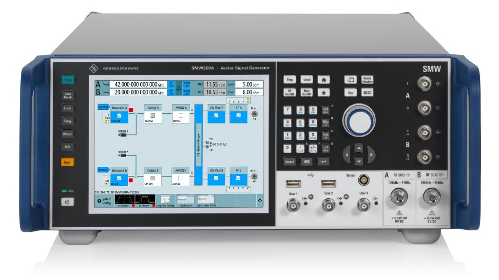
SMW200A.

The SMW200A is a high-end vector signal generator designed for advanced wireless test and measurement applications.

Its support for modern standards such as LTE and 5G, as well as its suitability for future 6G research, makes it a strong platform for realistic channel emulation.

Key Capabilities
  • Advanced MIMO signal generation and fading simulation
  • Support for up to 8 transmit/receive antennas or two independent 2×2 MIMO systems
  • Up to 4 fading blocks with up to 12 dynamic paths each
  • Support for standardized 3GPP channel models and user-defined fading scenarios
Why It Matters for This Project
The SMW200A provides the flexibility required to integrate externally generated channel data and reproduce realistic propagation scenarios for user-equipment testing.

Ansys Perceive EM Demo Scenario

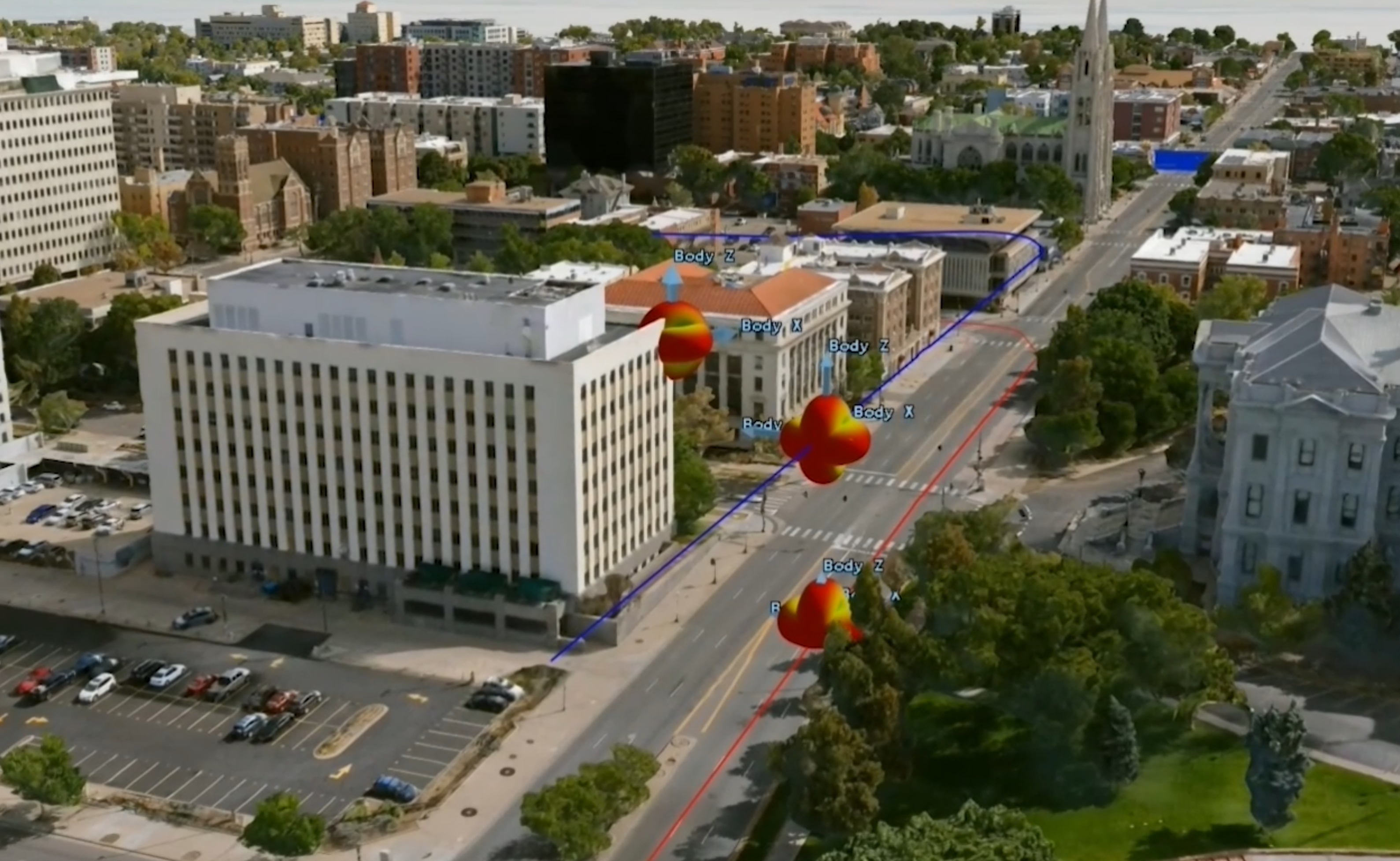
Ansys Perceive EM scenario snapshot.
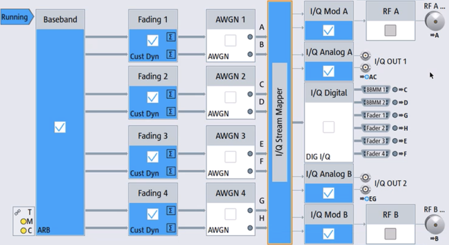
SMW200A configuration for the simulated scenario.

One scenario in the demonstration application was generated using Ansys Perceive EM.

The scenario models an urban environment with two mobile users: a ground vehicle and an airborne drone, both receiving signals from a base station mounted on a tall building.

This creates a realistic multi-user propagation environment with distinct fading conditions for each receiver.

SMW200A Configuration
The instrument is configured as a 4×2×2 MIMO system and uses all available fading resources: 24 paths per user, split across two fading blocks.
Device Integration
By converting the ray-tracing output into an SMW200A-compatible format, the simulated propagation environment can be reproduced directly on the instrument for realistic receiver testing.

Overall Objective

The goal of the demonstration application is to provide a user-friendly interface for controlling the Rohde & Schwarz SMW200A and replaying simulation-based wireless scenarios.

Target Workflow
  1. Select a predefined simulation scenario in the GUI
  2. Connect remotely to the SMW200A
  3. Automatically configure the instrument with scenario-specific parameters
  4. Start synchronized playback of the RF signal and scenario visualization
Expected Result
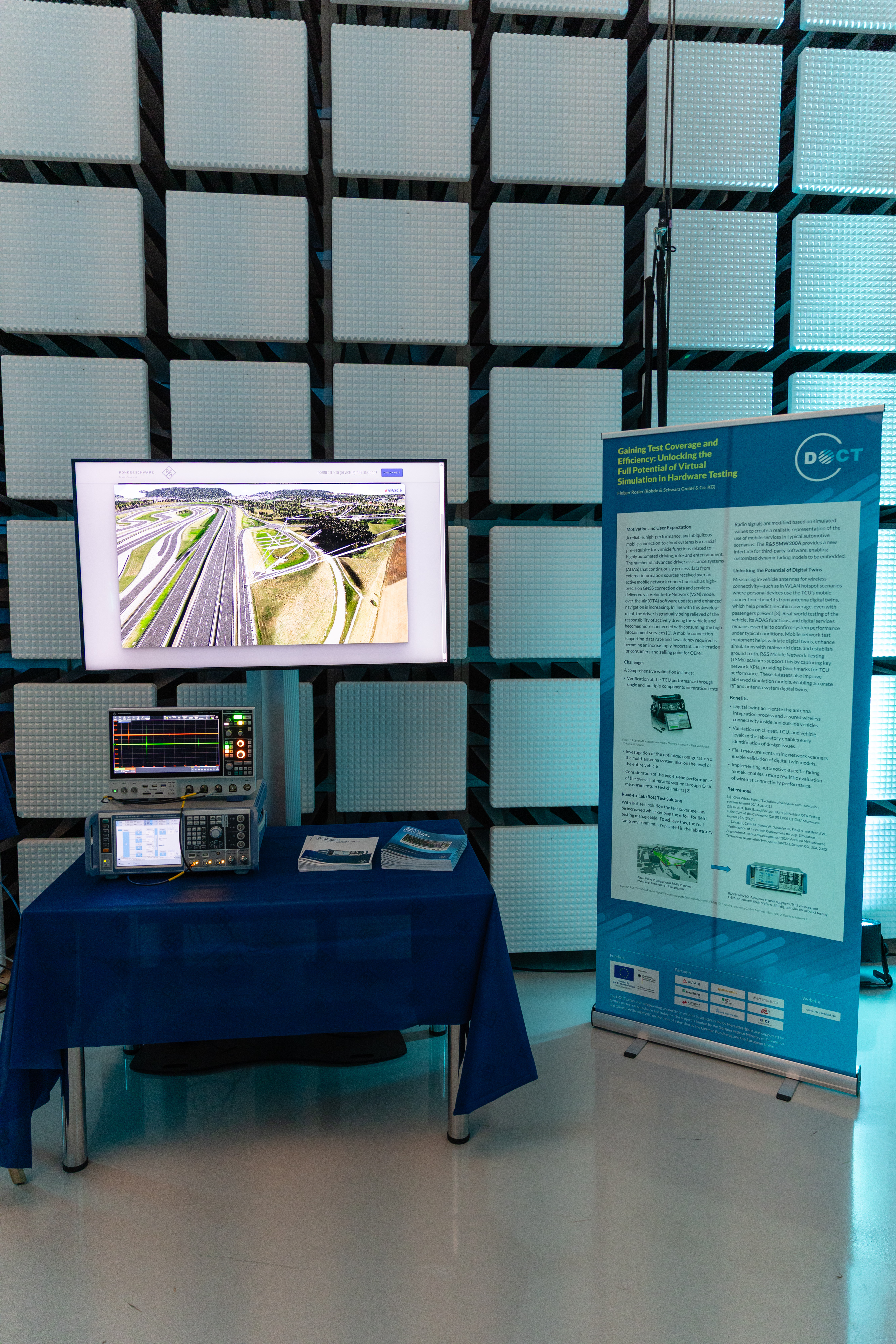
During playback, the SMW200A generates the corresponding RF signals in real time, while the GUI displays a synchronized video of the simulated scenario. The generated signals can be monitored externally, e.g., using an oscilloscope.

Why Flask?

The SMW200A supports remote control via SCPI and provides an official Python API, making Python the natural choice for the application backend.

Why a Web-Based GUI?
Instead of a desktop GUI built with tools such as Tkinter or PyQt, the project uses a browser-based frontend with HTML, CSS, and JavaScript.

This provides greater flexibility in layout, styling, extensibility, and user interaction.

Popular Python web frameworks:

Django
Powerful full-stack framework with built-in ORM and admin tooling, but heavier than needed for this prototype.
Flask
Lightweight, modular, and easy to integrate with a custom frontend. Chosen for rapid prototyping.
FastAPI
Modern and efficient, with strong asynchronous support. Likely the better long-term option.
Decision
Flask offered the fastest path to a working prototype as it is lightweight and, simple to set up, while FastAPI appears more attractive for future extensions.

Flask Application Structure

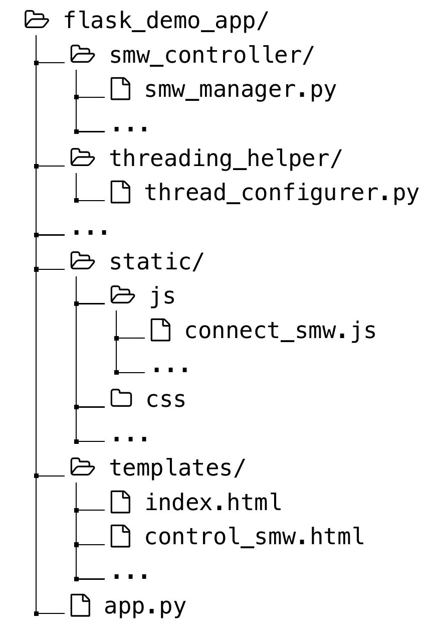
Project structure.

The demonstration application uses a lightweight Flask backend to connect browser-based user interaction with Python-based SMW200A control.

Core Flask Concepts Used
  • Routes map URL paths to Python functions
  • Templates render HTML pages via render_template()
  • Sessions store connection state such as the SMW IP address
  • Static files provide JavaScript, CSS, and images
Application Layout
The project follows the standard Flask structure with: app.py for routing logic, a templates/ directory for HTML pages, and a static/ directory for frontend assets.

Navigation and Session Logic

The application currently exposes two main pages:

Pages
  1. Index Page (index.html) Used to enter the static IP address of the SMW200A.
  2. Scenario Control Page (control_smw.html) Used to configure and run simulation scenarios after a successful connection.

Access to the scenario page is protected by the Flask session: the user is redirected unless a valid SMW connection is available.

Integration Architecture

Demo Application Integration Architecture Architecture diagram showing browser GUI, Flask backend, scenario assets, and Rohde and Schwarz SMW200A integration. Browser GUI HTML / CSS / JavaScript scenario selection connect / configure / play Flask Backend routing + templates session management threaded configuration tasks Flask-SocketIO feedback Scenario Assets simulation output configuration data video playback assets R&S SMW200A SCPI / Python API automatic configuration RF playback generation Measurement oscilloscope / observation HTTP requests HTML + SocketIO updates load scenario status + metadata SCPI / Python API control RF output
Architecture diagram showing browser GUI, Flask backend, scenario assets, and Rohde and Schwarz SMW200A integration. Configuration is handled in the backend; playback is triggered by the user and synchronized with scenario visualization.
Two Main Execution Stages
  1. Configuration Phase: The selected scenario is translated into SMW parameters and uploaded to the instrument. Depending on scenario complexity, this can take up to 2 minutes.
  2. Playback Phase: After configuration, the SMW waits in standby until the user starts playback. Signal generation then runs continuously until explicitly stopped.
Frontend Requirements
  • Show live configuration progress
  • Allow explicit start/stop control
  • Prevent unintended playback during setup
Backend Solution
Long-running operations are handled in separate Python threads, while Flask-SocketIO provides real-time bidirectional communication between the backend and the browser frontend.

Integration Architecture

Running the demo app is divided into two main stages
  1. Configuration Phase: The SMW is configured based on the selected scenario parameters. This stage may take up to 2 minutes, depending on scenario complexity.
  2. Playback Phase: Once configured, the SMW enters a standby state, awaiting a user-triggered "play" command. The signal output should loop endlessly until the user issues a stop command.
To ensure a responsive user experience, the app should:
  1. Provide live feedback on the configuration status.
  2. Allow user control over starting and stopping playback.
  3. Prevent unintentional triggering during configuration.

These requirements are addressed in the backend using Python threading to handle long-running tasks and Flask-SocketIO for real-time communication between the server and the browser-based frontend.

The Demo